Introduction to Diaphragm design.
1. Overview of Diaphragms
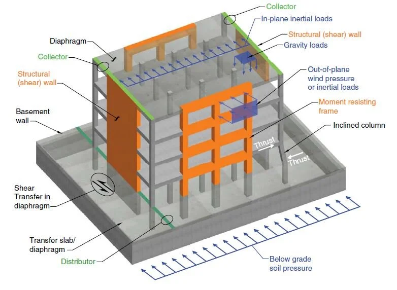
A diaphragm is a horizontal or sloped structural system that transmits lateral forces to the vertical elements of the Lateral Force-Resisting System (LFRS). Typically, diaphragms are provided by the floor and roof systems of a building. However, in some cases, independent horizontal bracing systems may also serve as diaphragms.
Diaphragms can be constructed using various materials, including:
Concrete slabs
Precast concrete floor planks with concrete topping
Metal decking with concrete fill
Roof sheathing
2. Roles of Diaphragms in Structures
The primary function of a diaphragm is to distribute lateral forces to the LFRS elements. Additionally, diaphragms:
Resist gravity loads.
Provide lateral support to vertical elements.
Transfer lateral inertial forces to vertical elements of the seismic force-resisting system.
Transfer forces through the diaphragm.
The largest diaphragm force transfers typically occur at offsets or discontinuities in the seismic-force-resisting system, such as:
Setbacks in the building profile
Podium levels at grade

3. Components of a Diaphragm
A. Chord
A chord resists all the flexural tension caused by in-plane bending due to lateral loads. If an edge beam is absent, the slab acts as a deep beam to resist flexural tension forces. Chord tension reinforcement should be placed within h/4 of the tension face, where h is the diaphragm width in the direction of analysis (as per ACI 318-14, Section 12.5.2.3).
B. Collector (Drag Struts or Ties)
Collectors are framing members that transfer diaphragm shear forces from unsupported areas to vertical resisting elements. The width of the collector may match the shear wall width, but in some cases, it must be wider. SEAOC 2005 recommends that the effective width (beff) should not exceed the wall width plus half the contact length between the diaphragm and the wall on either side.

4. Behavior of Diaphragms
A diaphragm behaves like a beam supported by lateral-resisting elements, where:
The floor or roof system acts as the beam web, resisting shear forces.
Chords function as flange elements, resisting axial tension and compression due to flexural forces.

5. Types of Diaphragms
Diaphragms are classified into three categories:
A. Rigid Diaphragms
A diaphragm is considered rigid if its aspect ratio is ≤3 for seismic loads and ≤2 for wind loads, provided the structure has no significant horizontal irregularities (ASCE 7-10, Section 12.3.1.2 and Section 27.5.4). The seismic story shear is distributed to LFRS elements based on their relative lateral stiffness.
B. Flexible Diaphragms
A diaphragm is flexible if its in-plane deflection under lateral loads is more than twice the average story drift of adjoining vertical LFRS elements. The seismic story shear is distributed based on the tributary area, with diaphragm deflections significantly greater than those of the LFRS.
C. Semi-Rigid Diaphragms
A semi-rigid diaphragm is modeled when significant in-plane deformation occurs or when required by code. This type of diaphragm simulates actual in-plane stiffness properties and behavior.


6. Code Requirements
Diaphragm seismic design is required for all buildings in Seismic Design Categories (SDC) B to F.
ASCE 7-10 (Section 12.10) mandates that diaphragms be designed for the greater of the following internal force calculations:
1. Equation 12.8.3
2. Empirical force equations
The detailing of diaphragms is generally independent of the LFRS type, meaning the R-value does not appear in upper and lower limit equations. ACI 318-14 (Section 18.12) applies to diaphragm design for buildings in SDC D to F, while Chapter 12 of ACI 318-14 applies to buildings in SDC B and C.


7. Diaphragm Modeling and Analysis Approaches
The internal forces in diaphragms can be determined using methods ranging from hand calculations to complex computer models, depending on the building’s irregularities. Common analysis methods include:
1. Equivalent beam model
2. Equivalent beam on spring model
3. Corrected equivalent beam model
4. Strut and tie model
5. Finite element model
8. Diaphragm Analysis in ETABS
Diaphragm forces can be obtained through section cuts in ETABS. More details can be found at: Diaphragm Forces in ETABS
For reinforced concrete (RC) diaphragms, stiffness modifiers typically range between 0.15 to 0.50 when analyzing for design-level earthquake demands (Nakaki, 2000).
References
1. ACI 318-14 – Building Code Requirements for Structural Concrete and Commentary
2. ASCE 7-10 – Minimum Design Loads for Buildings and Other Structures
3. NEHRP Seismic Design Technical Brief No. 3
An introduction to P-Delta effects in structural engineering.

Common structural engineers mistakes in the Saudi Building Code.
